Understanding Coordinate System Labels in ArcGIS Pro
Coordinate systems are fundamental for accurate mapping and spatial analysis. Each dataset in a map or scene can have its own coordinate system, which defines how the data's coordinates relate to locations on the Earth's surface.
This article will walk you through the steps to understand coordinate systems labels in ArcGIS Pro.
Software requirement(s):
- ArcGIS Pro 3.2.2
- Each layer has a coordinate system (CS).
- Each dataset should have a label that matches the x-y values in the file.
- Labels may be viewed in the Layer's Properties or the Catalog Pane.
- Labels always have a Geographic Coordinate System (GCS), because every CS is based on a GCS.
- Labels may also have a projection and its parameters.
Do I need to measure anything? If you say yes to this question, then you need to project your dataset. Projecting a dataset that has a GCS will convert its degrees of latitude and longitude into a measurable unit (meter, foot).
Accessing Coordinate System Labels for Layers in ArcGIS Pro
1. Open ArcGIS Pro and Load a Project:
Launch ArcGIS Pro and open an existing project or create a new one.
2. Add or Select a Layer:
- Add a layer to the map by dragging it from the Catalog pane or by using the Add Data button.
- Select the layer you want to inspect in the Contents pane.
3. Open Layer Properties:
- Right-click on the layer in the Contents pane.
- Select Properties from the context menu to open the Layer Properties dialog.

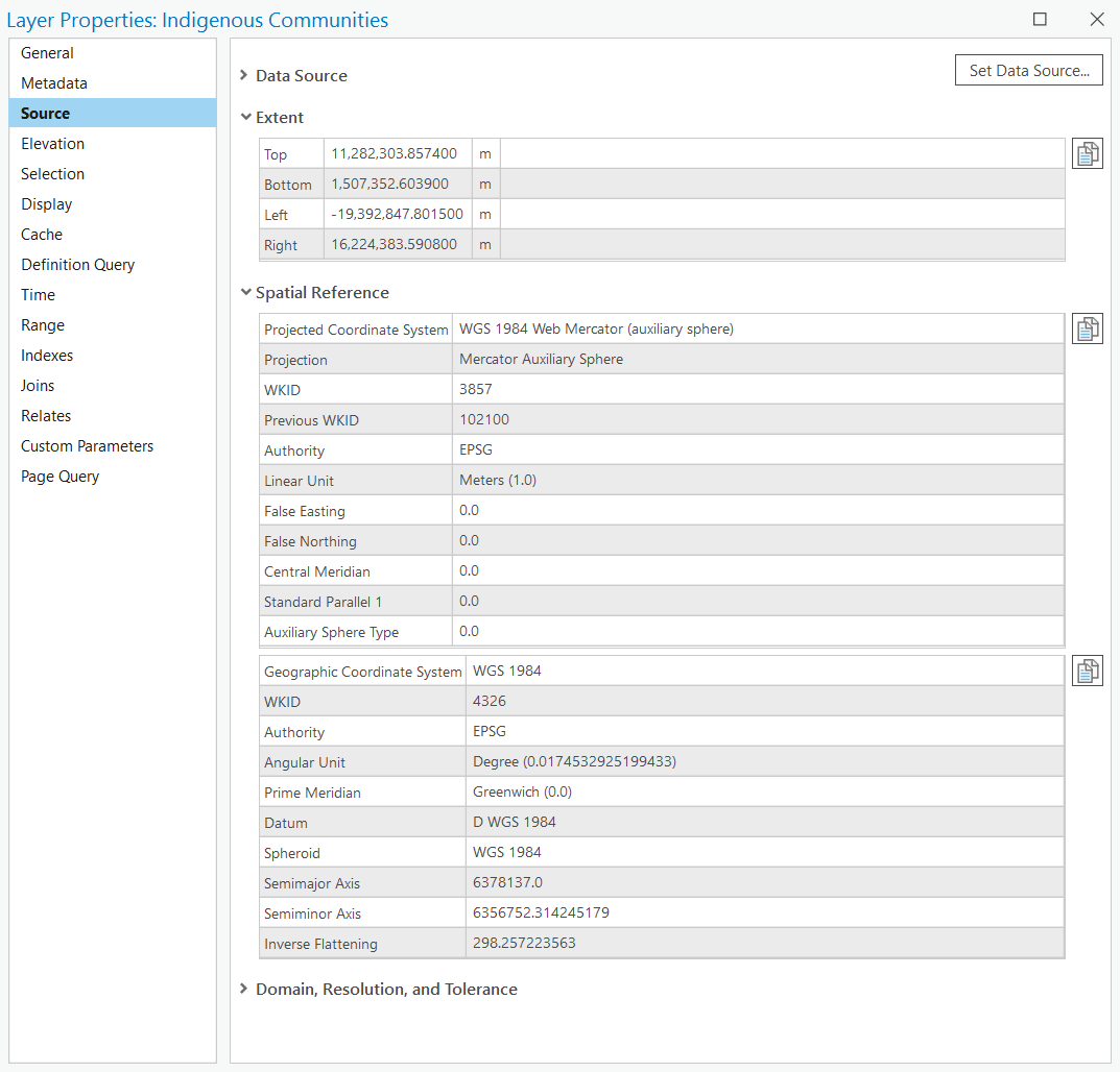
4. Navigate to the Source Tab:
- In the Layer Properties dialog, click on the Source tab.
- Under the Source tab, you’ll find information about the layer’s data source, including its coordinate system and extent.
Parameters for Geographic Coordinate Systems (GCS)
A Geographic Coordinate System uses a three-dimensional spherical surface to define locations on the Earth.
- The Extent
In a GCS, the extent defines the geographic area covered by a dataset, specified using angular units such as degrees of latitude and longitude. The extent is crucial for understanding the spatial coverage of the data and is defined by the minimum and maximum coordinates in both dimensions.
| Boundary | Coordinate | Description |
| Top | ymax | Maximum y-coordinate (northern boundary) |
| Bottom | ymin | Minimum y-coordinate (southern boundary) |
| Left | xmin | Minimum x-coordinate (western boundary) |
| Right | xmax | Maximum x-coordinate (eastern boundary) |
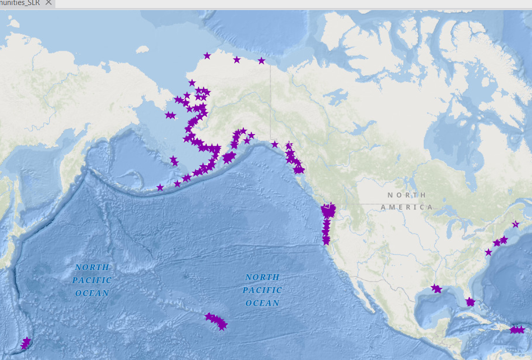
For example, the extent below (locations of indigenous communities in US and territories) ranges from -174.208916 degrees to 145.746118 degrees of longitude and from 13.416463 degrees to 70,646001 degrees of latitude, indicating that the dataset covers a specific region on the Earth's surface.
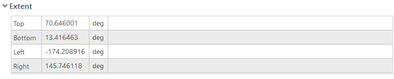

Properly defined extents are essential for accurately displaying and analysis spatial data within a GCS or a PCS, as they ensure that the data aligns correctly with other spatial datasets and maps.
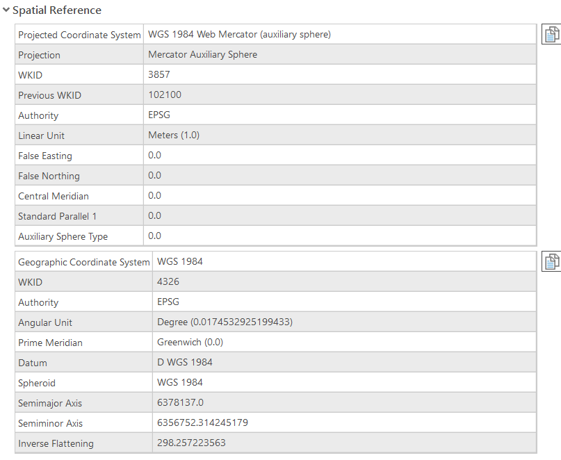
- The Spatial Reference (1)
The spatial reference for a dataset/layer is a critical property that defines how the geographic data is projected and aligned on the Earth's surface. The spatial reference includes both the coordinate system(s) and the extent of the data.
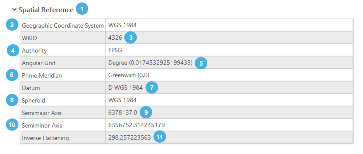
Key parameters for a GCS
| Parameter | Value |
| 2 | The name of the Geographic Coordinate System (e.g. WGS 1984, NAD 1983). |
| 3 | Well-known ID, unique identifier for the coordinate system. |
| 4 | The organization that defines and maintains the coordinate system. (e.g. EPSG stands for European Petroleum Survey group). |
| 5 | The unit of measure for angular coordinates, typically degrees for geographic coordinates systems. |
| 6 | The reference meridian for the coordinate system, usually Greenwich for most global systems (zero-longitude line). |
| 7 | The reference datum for the coordinate system, which defines the position of the spheroid relative to the Earth's center. Common datums include WGS 1984 and NAD 1983. |
| 8 | The mathematical model of the Earth's shape used by the datum. |
| 9 | The radius of the Earth at the Equator, a defining parameter of the spheroid. |
| 10 | The radius of the Earth at the poles, another defining parameter of the spheroid. |
| 11 | A measure of the flattening of the spheroid, calculated as the reciprocal of the flattening factor. |
Parameters for Projected Coordinate Systems (PCS)
A Projected Coordinate System uses a mathematical transformation to project locations from the Earth’s curved surface onto a flat plane.
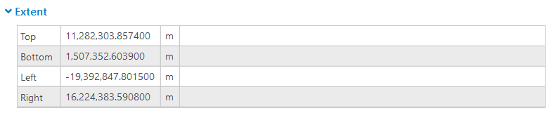
- The Extent
Similarly to the GCS, the PCS extent defines the geographic area covered by the layer, specified by the minimum and maximum x and y coordinates.
The extent of a layer is defined by the minimum and maximum coordinates in a given CS, specifically using the terms like easting and northing rather than cardinal directions. This is because the easting and northing refer to the coordinates in a grid system used by PCS, which provide a more precise and standardized way to define locations on a flat map.
- Easting (xmin and xmax): These coordinates refer to the distance eastwards from a define meridian (usually the central meridian of the projection). The minimum easting (xmin) represents the westernmost boundary), while the maximum easting (xmax) represents the easternmost boundary of the dataset.
- Northing (ymin and ymax): These coordinates refer to the distance northwards from a defined baseline (usually the Equator). the minimum northing (ymin) represents the southernmost boundary, while the maximum northing (ymax) represents the northernmost boundary of the dataset.
Using easting and northing is important because:
- Precision: Easting and northing coordinates provide precise numerical values that are essential for accurate mapping and spatial analysis. These values are expressed in linear units (e.g. meters and feet), which offer a consistent and measurable way to define positions on a map.
- Standardization: PCS rely on a grid-based approach, which is standardized and widely used in various mapping applications. This standardization ensures that coordinates are uniformly understood and interpreted across different GIS platforms and datasets.
- Clarity in Projections: In projected maps, the terms south, west, east, and north can become ambiguous, especially when dealing with large or rotated extents. Easting and northing remove this ambiguity by providing a clear and direct reference to the grid system used in the projection.
| Boundary | Coordinate | Description |
| Top | ymax | Maximum y-coordinate (northing) |
| Bottom | ymin | Minimum y-coordinate (northing) |
| Left | xmin | Minimum x-coordinate (easting) |
| Right | xmax | Maximum x-coordinate (easting) |
- The Spatial Reference
In ArcGIS Pro, and in GIS Software in general, the spatial reference for a projected layer/dataset includes two CS labels: one for the GCS and one for the PCS.
- The GCS defines the foundational framework of the Earth's shape using a datum, spheroid, and angular units like degrees of latitude and longitude (see above). This system ensures that the data accuracy reflects the real-world geography.
- The PCS, on the other hand, transforms these spherical coordinates into a flat, two-dimensional plane for mapping and analysis, using parameters such as the central meridian, false easting, false northing, and linear units like meters or feet.
This dual labeling is essential because it allows for precise and accurate spatial representation. The GCS ensures that the fundamental geographic relationships are maintained, while the PCS enables practical mapmaking and spatial analysis on a flat surface.
Understanding and correctly managing these labels ensures that spatial data is consistently and accurately projected, preventing misalignment issues and enhancing the reliability of geographic analyses and decision-making processes in GIS Projects.
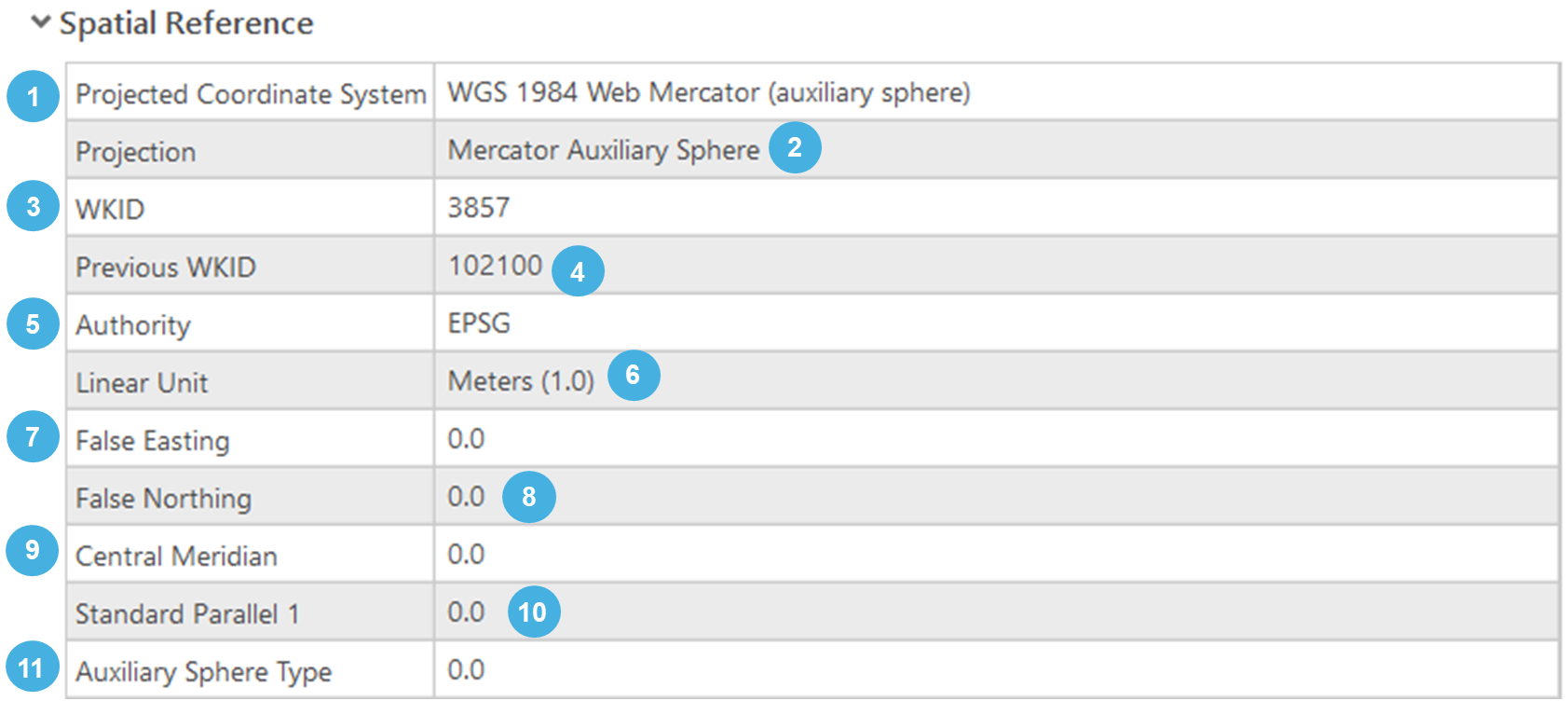
Key parameters for a PCS
| Parameter | Value |
| 1 | The name of the projected coordinate system. |
| 2 | The method used to project the coordinates from the spheroid (ellipsoid) to a flat plane. |
| 3 | Well-known ID, unique identifier for the coordinate system. |
| 4 | Previous Well-Known ID used for the coordinate system. |
| 5 | The organization that defines and maintains the coordinate system. (e.g. EPSG stands for European Petroleum Survey group). |
| 6 | The unit of measure for the projected coordinates. |
| 7 | A value added to all x-coordinates to ensure that they are positive. |
| 8 | A value added to all y-coordinates to ensure that they are positive. |
| 9 | The longitude of the central meridian, used as the origin for the x-coordinates. |
| 10 | The latitude (s) at which the scale is true (not applicable for Mercator projection, which uses the equator). Can include one or two standard parallels. |
| 11 | The type of auxiliary sphere used in the projection. |
The inclusion of a Previous WKID (Well-Known ID) serves several important purposes:
1. Historical Compatibility
- Transition and updates
Coordinate systems and their definitions can evolve over time. As standards are updated or refined, new WKIDs may be assigned to reflect these changes. Including the previous WKID ensures compatibility with older datasets and software that still use the former identifier.
- Consistency Across Versions
It helps users maintain consistency across different versions of software and datasets, ensuring that older data can still be correctly interpreted and utilized in newer environments.
2. Data Interoperability
- Cross-Platform Use
GIS applications and datasets from different platforms or time periods might reference the coordinate system using the previous WKID. Having both the current and previous WKID allows for seamless data exchange and interoperability.
- Legacy Systems
Some legacy systems or software might still use the old WKID. Providing the previous WKID ensures that data can be accurately used across these systems without confusion or errors.
3. Ease of Transition
User Adaptation
For users transitioning from older systems or datasets to newer ones, the inclusion of the previous WKID aids in understanding and adapting to the changes. It provides a clear reference to what the coordinate system was previously known as.
Documentation and Support
It assists in documentation and technical support, where historical references to coordinate systems might be necessary to resolve issues or understand data lineage.
Example of Previous WKID in Use
WGS 1984 Web Mercator (Auxiliary Sphere):
- Current WKID: 3857
- Previous WKID: 102100
In this example, the previous WKID 102100 was commonly used in older versions of GIS software and datasets. With the update to the EPSG database, the WKID 3857 was introduced to standardize the coordinate system under the new EPSG guidelines. Including both IDs ensures that data referencing either ID can be correctly understood and utilized.
Summary
By accessing the Layer Properties in ArcGIS Pro, you can view and understand the coordinate system and extent of your data layers.
This includes:
• Geographic Coordinate System: Parameters like datum, spheroid, prime meridian, and angular unit.
• Projected Coordinate System: Parameters like projection type, false easting/northing, central meridian, scale factor, latitude of origin, and linear unit.
• Extent: The geographic area covered by the layer, defined by the minimum and maximum coordinates.
Understanding these parameters helps ensure that your spatial data is correctly interpreted and displayed, which is crucial for accurate mapping and analysis.
Tips and Tricks for Understanding Coordinate System Labels in ArcGIS Pro
Understanding CS labels in ArcGIS Pro is crucial for accurate mapping and spatial analysis. Here are some tips and tricks to help you navigate and manage coordinate systems effectively:
1. Check Layer Properties Regularly
- Access Layer Properties: Right-click on a layer in the Contents pane and select "Properties." Go to the "Source" tab to view the coordinate system.
- Verify Coordinate Systems: Ensure that each layer in your map has the correct coordinate system to prevent misalignment and projection issues.
2. Understand the Dual Labels for Projected Layers
- GCS and PCS: Recognize that a PCS includes both the GCS and the PCS. The GCS defines the shape of the Earth, while the PCS transforms this shape onto a flat plane.
- Two Labels: Pay attention to both labels in the layer properties to understand how data is projected and displayed.
3. Use the Project and Define Projection Tools Appropriately
- Define Projection Tool: Use this tool to assign or correct the coordinate system metadata without changing the data’s coordinates. Ideal for datasets with undefined or incorrect projections.
- Project Tool: Use this tool to convert data from one coordinate system to another, recalculating the coordinates. This is essential for standardizing datasets to a common coordinate system for analysis.
4. Leverage the Search Function
- Search Coordinate Systems: Use the search function in the coordinate system selection dialog to quickly find and apply the appropriate coordinate system based on name, WKID, or keywords.
- Favorites and Recent: Utilize the "Favorites" and "Recent" tabs to quickly access commonly used coordinate systems.
5. Understand WKID (Well-Known ID)
- Identify Coordinate Systems: Each coordinate system has a unique WKID that simplifies identification and use. Familiarize yourself with common WKIDs, such as 4326 for WGS 1984 (GCS), 3857 for Web Mercator (PCS), 4269 for NAD 1983 (GCS)...
- Previous WKID: Be aware of the previous WKID for legacy data compatibility. This helps when working with older datasets or transitioning between different versions of coordinate systems.
6. Inspect the Extent
- View Extent Coordinates: Check the extent values (xmin, ymin, xmax, ymax) in the Layer Properties under the Source tab to understand the geographic coverage of your data.
- Units Matter: For GCS, extents are in degrees (longitude and latitude), while for PCS, they are in linear units like meters or feet.
7. Handle Geographic Transformations
- Transformation Options: When projecting between coordinate systems with different datums, ArcGIS Pro may prompt you to select a geographic transformation. Choose the appropriate transformation based on the geographic area and accuracy requirements.
- Transformation Library: Familiarize yourself with common transformations for your region and add them to your favorites for quick access.
8. Use Basemaps for Visual Verification
- Overlay with Basemaps: Add a basemap to your project to visually verify the alignment and projection of your data layers. This helps identify any misalignment issues early.
- Match Coordinate Systems: Ensure your basemap and data layers share the same coordinate system or use on-the-fly projection to align them.
9. Documentation and Resources
- ArcGIS Pro Help: Utilize the extensive documentation and resources available in ArcGIS Pro’s help system to understand coordinate systems and their parameters.
- NTGISC Support: Reach out to NTGISC support for assistance with complex coordinate system issues.
10. Practice with Real Data
- Experiment: Practice defining and projecting coordinate systems with sample datasets to build confidence and proficiency.
- Analyze Results: Analyze the results of your projections and transformations to understand the effects on your data’s accuracy and alignment.
By following these tips and tricks, you can effectively manage and understand coordinate system labels in ArcGIS Pro, ensuring accurate spatial data representation and analysis.
We hope that this article has been helpful! If you have any feedback or questions, please feel free to send us an email or connect with us for a chat. The NTGISC team is here to assist you further!